- Get link
- X
- Other Apps
- Get link
- X
- Other Apps
This is the second part of the series called "SIM900A 2G module + Hologram SIM card = winning combination in category dirt cheap?". In the previous post I demonstrated how to perform some essential operations with SIM900A GPRS module: send AT commands to determine firmware version and baud rate, and most importantly reflash it, unlocking it to operate outside of Asian countries.
Today I'll show you how to make use of Hologram SIM card and its free 1Mb per month quota. We'll take some sensor measurements (fake them, to be exact) and send them to Internet via Thingspeak.
Hologram SIM card
If you haven't ordered and registered Hologram SIM at the time of reading the first part, I'll show where and how to order it, register it and find out information essential to connect to 2G GPRS network.- Navigate to their website. You'll have to register an account to order a free SIM card. Don't worry - it's not just some useless account on another website, you'll use it to get access to your dashboard with detailed information and stats about your SIM cards and data usage.
- Order a SIM card - the one that has one free megabyte of data per month. The shipping was free as well at the time when I ordered it, not sure about now. As is evident from its name, it's supposed to have coverage around the globe, although I don't see how it's possible in 3/4G only countries. Those who successfully used this SIM in a country where 2G has been phased out, please let me know in the comments section.
- After some time of waiting, the envelope with your SIM will finally turn up in the mailbox. Now you'll have to register it. Go to the dashboard.hologram.io and activation button will be in plain sight:
- Select the Maker plan, if you will (it will allow up to 25 active SIM cards), although you are free to pick any other one if it fits you better.
- The next step will give you insight on the financial aspects of your plan. I've highlighted two most important things on my plan's page: 1) It includes 1Mb a month for free. 2) The limit on data usage can be set by you - that means if you don't want to pay, you won't (set the limit to 1Mb), or you can go unlimited and pay 40 cents for each megabyte after the first one.
- We've finally gotten to activation. 1) Enter the number of your SIM(s). 2) Enter a name - it's actually a kind of prefix for this batch of SIM cards.
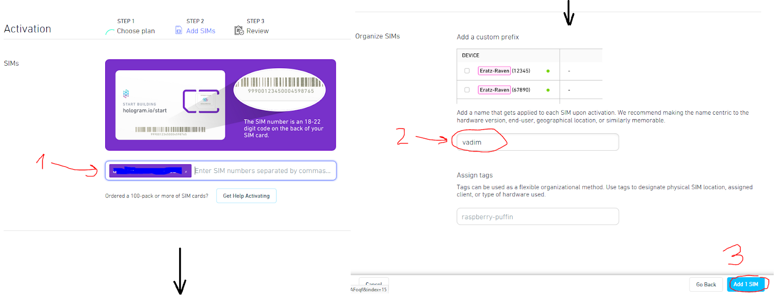
- The final page with all details of registration contains yet another reassuring thing for people who went for the free 1Mb SIM: you won't be charged unless you add a payment method. Make sure that everything you've entered is correct and click "Activate N SIM" button:
- Activation takes about 10 seconds, wait for it...
Patience is a virtue! This screenshot means that your request to activate your sim is being processed. |
Finished! |
- If you've ever connected any 2G modem to GPRS network, you're probably wondering where to look up APN, user name and password for connection. They are right there, just click on your device record in "Manage" table.
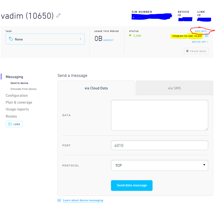
APN is "hologram", user name and password empty. |
That was Hologram SIM card preparation - now it's ready to connect to 2G network, and you know all you need to gently push it toward this course of action..
Thingspeak
Making a channel in Thingspeak to publish your data from anywhere with access to Internet is quite easy. Obviously, you have to open Thingspeak website and register:- Create a new channel - one for each device sending data.
- Fill in the details of your channel. You can publish up to 8 distinct measurements for one channel (device) e.g. temperature, humidity, etc. We'll settle on just one value for our experiments.
- After successfully creating your channel, you want to know how to post some data into it. Go to "API Keys" section - there are examples of HTTP requests for every possible scenario. Also, take note of your "Write API Key" - we're going to need that for our next step.
Publishing fake measurements to Thingspeak via GPRS
Let's see if we can at long last send something to the server. After completing the first part of this tutorial we have our SIM900A modem ready to connect to any 2G network provider, and we've just got ourselves the SIM card with 1Mb of free data per month and a Thingspeak channel to publish numbers to. Yeah, we're definitely all set.In part 1 we changed the baud rate to 115200 to speed up the firmware upload process, but our top priority now is absence of errors during transmission. Lower baud rates are better suited for that purpose, therefore I suggest as soon as you're connected to your module, the first command you issue is AT+IPR=9600.
I bet that by now, your hands are itching to upload something to Arduino! What I did before actually connecting hardware and writing the code, though, was manually enter all the required commands to get acquainted with the flow. You can skip straight to schematics of mock sensor data publisher, but I recommend going through the same steps to get a better feeling of what's happening under the hood.
A word of advice before we go on: GPRS operations are especially current-consuming, that's why I soldered and hot-glued yet another huge capacitor on top of my module:
In the case when your module starts resetting during GPRS connection, it's a transparent indication that you need to do it too. How to tell if your module is resetting itself? You'll see the startup sequence in your console window:
1 2 3 4 5 6 7 | RDY +CFUN: 1 +CPIN: READY Call Ready |
Now, on to the whole GPRS command sequence. You can take the the same auto-detection sketch we used in part 1:
And this is how you set up 2G connection and send HTTP requests |
1 2 3 4 5 6 7 8 9 10 11 12 13 14 15 16 17 18 19 20 21 22 23 24 25 26 27 28 29 30 31 32 33 34 35 36 37 38 39 40 41 42 | AT serial speed tester Testing with RX on pin 8 and TX on pin 9 Testing 1200 baud... Received: [abracadabra] Testing 2400 baud... Received: [abracadabra] Testing 4800 baud... Received: [abracadabra] Testing 9600 baud... Received: [AT OK ] Your speed is 9600 baud You can send any number of commands to your module now ------------- AT+CGATT? +CGATT: 1 OK AT+CSTT="hologram" OK AT+CIICR OK AT+CIFSR 10.52.146.242 AT+CIPSTART="tcp","api.thingspeak.com",80 OK CONNECT OK AT+CIPSEND=78 SEND OK 3 CLOSED |
78 in AT+CIPSEND=78 stands for the length of the data you're about to send, including trailing \r\n - for real API key it's going to be 73 + the length of field1.
As soon as you're done typing the last command, you should be able to see a new data point in Thingspeak device page:
At this point we are sure that this approach of sending sensor measurements works (even if you decided to skip straight to microcontroller implementation - believe me, it works).
Let's proceed with assembling everything according to the schematic and coding. We'll use the same hardware as what's in part 1, plus one pushbutton and one potentiometer:
There's never enough power pins on Arduino. I splashed a huge blob of solder on female 2.54mm pin header to make an impromptu distributing hub. |
The schematic diagram is as simple as they go: potentiometer provides mock sensor data, and pushbutton serves as a trigger to send one measurement to Thingspeak.
Next comes the code:
1 2 3 4 5 6 7 8 9 10 11 12 13 14 15 16 17 18 19 20 21 22 23 24 25 26 27 28 29 30 31 32 33 34 35 36 37 38 39 40 41 42 43 44 45 46 47 48 49 50 51 52 53 54 55 56 57 58 59 60 61 62 63 64 65 66 67 68 69 70 71 72 73 74 75 76 77 78 79 80 81 82 83 84 85 86 87 88 89 90 91 92 93 94 95 96 97 98 99 100 101 102 103 104 105 106 107 108 109 110 111 112 113 114 115 116 117 118 119 120 121 122 123 124 125 126 127 128 129 130 131 132 133 134 135 136 137 138 139 140 141 142 143 144 145 146 147 148 149 150 151 152 153 154 155 156 157 158 159 160 161 162 163 164 165 166 167 168 169 170 171 172 173 174 175 176 177 178 179 180 181 182 183 184 185 186 187 188 189 190 191 192 193 194 195 196 197 198 199 200 201 202 203 204 205 206 207 208 209 210 211 212 213 214 215 216 217 218 219 220 221 222 223 224 225 226 227 228 229 230 231 232 233 234 235 236 237 238 239 240 241 242 243 244 245 246 247 248 249 250 251 252 253 254 255 256 257 258 259 260 261 262 263 264 265 266 267 268 269 270 271 272 273 274 275 276 277 278 279 280 281 282 283 284 285 286 287 288 289 290 291 292 293 294 295 296 297 298 | //#define DEBUG #include <Bounce2.h> #include <AltSoftSerial.h> //------------------------------------------------------------ // Settings #define USBSERIAL_BAUD 9600 #define MODEM_BAUD 9600 #define BUTTON_PIN 2 #define SENSOR_PIN A0 #define SERIAL_TIMEOUT 500 #define BETWEEN_ATTEMPTS 1000 #define ANALOG_THRESHOLD 15 const String APN = "hologram" ; // End of settings //------------------------------------------------------------ //------------------------------------------------------------ // Object and variable definitions // AltSoftSerial always uses these pins: // // Board Transmit Receive PWM Unusable // ----- -------- ------- ------------ // Arduino Uno 9 8 10 AltSoftSerial modemSerial; struct AtResult { bool found; String response; }; Bounce button = Bounce(); bool buttonValue; uint16_t sensorValue; const String OK = "OK" ; const String EMPTY_STRING = "" ; // End of object and variable definitions //------------------------------------------------------------ void setup() { Serial.begin(USBSERIAL_BAUD); modemSerial.begin(MODEM_BAUD); digitalWrite(LED_BUILTIN, 0 ); while (!setupGprs()) ; pinMode(BUTTON_PIN, INPUT_PULLUP); button.attach(BUTTON_PIN); button.interval( 5 ); buttonValue = button.read(); pinMode(SENSOR_PIN, INPUT); } void loop() { button.update(); if (button.read() != buttonValue) { // press or release event buttonValue = !buttonValue; if (buttonValue) { // do it on button release only Serial.println(F( "Connecting to Thingspeak server (AT+CIPSTART)..." )); if (sendAndWait( "AT+CIPSTART=\"tcp\",\"api.thingspeak.com\",\"80\"" , "CONNECT OK" , 6 ).found) { Serial.println(F( "Connected!" )); } else { Serial.println(); Serial.println(F( "[Error] Can't connect to Thingspeak server." )); return ; } Serial.println(F( "Start sending data (AT+CIPSEND)..." )); int measurement = analogRead(SENSOR_PIN); String toSend = "GET " ; toSend += URL; toSend += measurement; int dataLength = toSend.length() + 2 ; // including \r\n if (sendAndWait( "AT+CIPSEND=" + String(dataLength), ">" , 8 ).found) { Serial.println(); Serial.println(F( "Got command prompt." )); } else { Serial.println(); Serial.println(F( "[Error] Can't start sending data" )); return ; } // Send the data, wait until the connection is closed. AtResult dataResponse = sendAndWait(toSend, "SEND OK" , 4 ); if (dataResponse.found) { if (!checkString(dataResponse.response, "CLOSED" )) { Serial.println(); if (sendAndWait( "AT+CIPCLOSE" , "CLOSE" , 4 ).found) { Serial.println(F( "Successfully closed the connection" )); } else { Serial.println(F( "[Warning] Couldn't close the connection for some reason..." )); } } Serial.print(F( "Sent sensor data: " )); Serial.println(measurement); } else { Serial.println(); Serial.println(F( "[Error] Didn't receive the confirmation of sending data." )); } } } // Show the current value of sensor in Serial. uint16_t newSensorValue = analogRead(SENSOR_PIN); if (abs(newSensorValue - sensorValue) > ANALOG_THRESHOLD) { Serial.print( "Sensor value: " ); Serial.println(newSensorValue); sensorValue = newSensorValue; } } //------------------------------------------------------------ // Custom functions bool setupGprs() { Serial.println(F( "1. Sanity check with AT command:" )); sendAndWaitIndefinitely( "AT" , OK, 1000 ); Serial.println(F( "Ready!" )); Serial.println(F( "2. Check if modem is attached to packet domain service (AT+CGATT)" )); AtResult cgatt = sendAndWait( "AT+CGATT?" , OK, 3 ); if (checkString(cgatt.response, "+CGATT: 1" )) { Serial.println(F( "Attached!" )); } else { Serial.println(F( "Not attached yet! Rectifying that..." )); if (sendAndWait( "AT+CGATT=1" , OK, 40 ).found) { Serial.println(F( "Attached successfully!" )); } else { Serial.println(F( "[Warning] Couldn't attach the modem to packet domain service." )); } } Serial.println(F( "3. Check and/or set APN Name (AT+CSTT)" )); AtResult cstt = sendAndWait( "AT+CSTT?" , OK, 3 ); bool isApnSet = checkString(cstt.response, APN); if (isApnSet) { Serial.print(F( "Already set to " )); Serial.println(APN); } else { Serial.print(F( "Setting APN name to " )); Serial.println(APN); if (sendAndWait( "AT+CSTT=\"" + APN + '\"' , OK, 5 ).found) { isApnSet = true ; Serial.print(F( "Done! APN name is " )); Serial.println(APN); } else { Serial.println(F( "[Warning] Can't set APN name." )); } } Serial.println(F( "4. Set up GPRS connection (AT+CIICR)" )); bool isGprsSet = sendAndWait( "AT+CIICR" , OK, 20 ).found; if (isGprsSet) { Serial.println(F( "Done!" )); } else { Serial.println(F( "[Warning] Can't set up GPRS connection." )); } Serial.println(F( "5. Get your IP address (AT+CIFSR)" )); String ipAddress = getMyIp( 3 ); if (ipAddress != EMPTY_STRING) { Serial.print(F( "Your address is: " )); Serial.println(ipAddress); } else { Serial.println(F( "Could not set up GPRS connection! Trying again..." )); return false ; } pinMode(LED_BUILTIN, OUTPUT); digitalWrite(LED_BUILTIN, 1 ); Serial.println(F( "Initialized! Press the button to send current measurement to server." )); return true ; } String getMyIp( int attempts) { modemSerial.setTimeout(SERIAL_TIMEOUT); if (attempts < 1 ) { attempts = 1 ; } modemSerialFlush(); String rawIp = EMPTY_STRING; modemSerial.println( "AT+CIFSR" ); for ( int i = 0 ; i < attempts; i++) { rawIp += modemSerial.readString(); if (parseIp(rawIp) != EMPTY_STRING) { return parseIp(rawIp); } newDelay(BETWEEN_ATTEMPTS); } return EMPTY_STRING; } String parseIp(String raw) { String ip = EMPTY_STRING; int currentNumber = 0 ; for ( int i = 0 ; i < raw.length(); i++) { if (!currentNumber && isDigit(raw.charAt(i))) { ip += raw.charAt(i); currentNumber = 1 ; continue ; } if (currentNumber) { if (isDigit(raw.charAt(i)) || raw.charAt(i) == '.' ) { ip += raw.charAt(i); if (raw.charAt(i) == '.' ) { currentNumber ++; } } else { break ; } } } if (currentNumber == 4 ) { return ip; } else { return EMPTY_STRING; } } AtResult sendAndWait(String cmd, String resp, int attempts) { struct AtResult atresult = { false , EMPTY_STRING}; modemSerial.setTimeout(SERIAL_TIMEOUT); if (attempts < 1 ) { attempts = 1 ; } modemSerialFlush(); modemSerial.println(cmd); for ( int i = 0 ; i < attempts; i++) { #ifdef DEBUG if (i > 0 ) { Serial.println(); Serial.print(F( "Attepmt " )); Serial.println(i + 1 ); } #endif atresult.response += modemSerial.readString(); #ifdef DEBUG Serial.print(atresult.response); #endif if (checkString(atresult.response, "ERROR" )) { atresult.found = false ; break ; } atresult.found = checkString(atresult.response, resp); if (atresult.found) { break ; } } #ifndef DEBUG Serial.print(atresult.response); #endif return atresult; } bool sendAndWaitIndefinitely(String cmd, String resp, int serialTimeout) { bool gotString = false ; modemSerial.setTimeout(serialTimeout); while (!gotString) { modemSerialFlush(); modemSerial.println(cmd); String serialResponse = modemSerial.readString(); Serial.print(serialResponse); gotString = checkString(serialResponse, resp); if (!gotString) { newDelay(BETWEEN_ATTEMPTS); } } } inline bool checkString(String val, String in) { return (val.indexOf(in) > - 1 ); } void newDelay( int ms) { modemSerial.setTimeout(ms); modemSerial.readString(); } void modemSerialFlush() { while (modemSerial.available()) { modemSerial.read(); } } |
Upload the code, open the Serial monitor and spin the potentiometer head to any value you desire. Push the button and watch it end up on Thingspeak servers:
1 2 3 4 5 6 7 8 9 10 11 12 13 14 15 16 17 18 19 20 21 22 23 24 25 26 27 28 29 30 31 32 33 34 35 36 37 38 39 40 41 42 43 44 45 46 47 48 49 50 51 52 53 54 55 56 57 58 59 60 61 62 63 64 65 66 67 68 69 70 71 72 73 74 75 76 77 78 79 80 81 | 1. Sanity check with AT command: AT OK Ready! 2. Check if modem is attached to packet domain service (AT+CGATT) AT+CGATT? +CGATT: 0 OK Not attached yet! Rectifying that... AT+CGATT=1 OK Attached successfully! 3. Check and/or set APN Name (AT+CSTT) AT+CSTT? +CSTT: "CMNET","","" OK Setting APN name to hologram AT+CSTT="hologram" OK Done! APN name is hologram 4. Set up GPRS connection (AT+CIICR) AT+CIICR OK Done! 5. Get your IP address (AT+CIFSR) Your address is: 10.52.146.242 Initialized! Press the button to send current measurement to server. Sensor value: 1021 Connecting to Thingspeak server (AT+CIPSTART)... AT+CIPSTART="tcp","api.thingspeak.com","80" OK CONNECT OK Connected! Start sending data (AT+CIPSEND)... AT+CIPSEND=76 > Got command prompt. SEND OK 20 AT+CIPCLOSE CLOSE OK Successfully closed the connection Sent sensor data: 1023 Sensor value: 1020 ... Sensor value: 572 Connecting to Thingspeak server (AT+CIPSTART)... AT+CIPSTART="tcp","api.thingspeak.com","80" OK CONNECT OK Connected! Start sending data (AT+CIPSEND)... AT+CIPSEND=75 > Got command prompt. SEND OK 21 AT+CIPCLOSE CLOSE OK Successfully closed the connection Sent sensor data: 577 |
The only question that remains is: How much measurements like this one can I upload in one month, under the limit of 1MB? Let's find out with the help of Hologram dashboard:
1 kilobyte of data is all it used! That means that 1 free megabyte is around 1000 sensor updates a month, or 32 a day. Not bad for a freebie, huh?
What can YOU do with this information? It's up to you to decide. The most viable idea of the device that I came up with is a remote solar- or hydro-powered sensor that just notifies you about some events and/or sends you updates on temperature/humidity/you name it.
Anyway, thanks for reading all the way to the end, and stay tuned for more exciting ideas about transforming mundane electronic parts into something useful!
Comments
Post a Comment