Solar panels are cool, right? All techniques of extracting energy from environment have always fascinated me, with solar panels standing out because of their inexpensiveness and ubiquity. I've been wanting to make something incorporating solar panels for ages, and finally got around to it.
What we'll be making today is a simple night light powered off solar energy. Yes, the same thing you see in gardening department of every hypermarket and gardening supply stores around the world.
 |
| What a neat idea! It only figures that it's already mass-produced. |
The difference is, we'll put a new spin on the old idea of solar lights by assembling the whole fixture inside a mason jar! Wait, why did you say "old news"?
Well, it didn't matter to me if it was new stuff or not, I still wanted to make a solar-powered night lamp. After about a month of attempts and toil smeared thin across 2 or 3 years (yes, I did stow this project away at the end of every summer, and I really had better things to do almost all of the time) I finally produced a viable result.
My build even had one distinction from the mason jar lamp mentioned above - instead of scavenging store-bought solar lamp we'll solder together our own Frankenstein's monster! That's more fun than just fitting Shenzhen-assembled PCB into another enclosure, right?
Before sharing the full building process with you, some pics of failed attempts are to follow:
 |
| One of my attempts utilized fairly complex logic incorporated in TI BQ25504 chip. It didn't work out due to the fact that this chip was designed to efficiently harvest lower energy than my solar panels provided. Also, overall design was too complex for such a simple task. |
 |
| Another mistake that I've made is trying to use up more energy than my solar panels could accumulate. 12 white LEDs depleted one fully charged lithium battery at a rate that proved to be too much to give even an evening of light. |
Ingredients
- One glass jar - any kind will do. Possible improvement for your build: make it frosted inside for better light diffusion.
 |
| Actually, the device we'll make can be hosted inside any plastic or glass container. |
- White LEDs and 56Ω or 68Ω resistors x3.
Possible variation for your design: get any color and any number of LEDs, then recalculate the current-limiting resistor value e.g.
here:
 |
| Calculating the value of series resistors for my setup. |
As you can see, the "perfect" resistor value for my arrangement is 68Ω, but I substituted it for 56Ω because slight variation in LED current won't matter much. It has to be close to 20mA is all.
Two solar panels in series-parallel connection will give a maximum of (8V - 0.2V of Schottky
diode drop). That's pushing the limits of TP4056 chip input voltage (see
datasheet), but it works okay for me. Regarding capacitors - the exact value is not important, just grab a couple of long electrolytic caps from the insides of some power supply. My schematic incorporates two 3300uF capacitors - that's enough - rated 6.3V - that's not enough! Grab some capacitors rated for at least
MaxVoltage*1.25,
MaxVoltage being the highest voltage you expect them being subjected to. 10 or 16 volts is probably fine for this case.
 |
| The black rectangle at the bottom right is 2 Schottky diodes in one package. |
- One lithium battery, one charger, one 47kΩ resistor (yeah, the third stripe on its body looks red on my picture, but it really is orange.), one 2N3904 PNP transistor and one switch.
- One solderless breadboard for prototyping and testing - strongly recommended! Even if you decide to just assemble a carbon copy of my device, there's still a solid chance of at least one of your components malfunctioning/being counterfeit. Breadboard your design before the final assembly.
- Two-component epoxy to plaster solar panel assembly to the lid of your jar. Get one in your local hardware store.
Finally, when every item on the list is checked off, we can get started!
 |
| Everything you'll need within electronics realm for this project. |
Schematics
The diagram is pretty straightforward - two panels are connected in series to produce a maximum of 8V, then in parallel to double (hopefully, in perfect conditions) output current.
The voltage is then fed to big capacitors to accumulate energy. Solar panels are a woeful current source - even 100mA of drain will collapse the voltage to near zero.
The energy extracted and stored in capacitors goes to battery charger (set to really low current to further guarantee absence of huge currents).
The rest of our circuit is just a PNP transistor switching LEDs ON when the current through base is LOW, and OFF when it's HIGH. Low current = low lighting, so that suits our purposes.
Testing:
First of all, we're going to have to modify our charger. According to
this other guy who tested TP4056-based charger boards (
datasheet), the factory-provided current setting resistor sets the charging current to 1A. That's good for wall warts (AC power supplies) but my solar panels wouldn't be able to put out more than 200mA even under perfect conditions!
This is why we needed an extra 47k resistor - it will set the charging current to 25mA.
This one modification should be enough to get to testing. Assemble everything on the breadboard according to schematics:
Now move the whole testing rig to the great outdoors!
 |
| It was a fine summer day, and my balcony was occupied by a weird octopus-like contraption... |
The purpose of this venture is to find out if your battery is adequately sized for your solar panel assembly. If it is:
a) The battery will be close to full charge (or even fully charged) every evening (near the end of solar day) - that's 4.2V.
b) It will be depleted (around 3 - 3.2V) at the end of night.
 |
| That's the proof that this thing works - at the middle of the day battery's voltage is close to full charge. |
Picking oversized battery will result in under-utilizing it's capacity. I.e. it's going to discharge during the night and only charge to 3.5V during the day - that's a sign that you have to find a battery with lower capacity.
After making sure your setup works we can stuff it into more permanent housing and solder it together, just as described below.
Assembly
- Solder LEDs and their corresponding resistors together into a self-sufficient lighting fixture that can be powered from a single lithium cell.
Note that I'm using tiny chip resistors instead of regular ones. That's not necessary but saves space and makes the lights look more artsy.
When you've made your unique lighting piece, you may test it individually with a simple button cell (e.g. CR2032). You probably want it to give off even light in all directions:
- Fit the panels together. I'm using a piece of solid core copper wire to make a semi-rigid construction which is then embedded into epoxy to finalize it.
 |
| Start by making two modules consisting of 2 panels each by connecting - terminal of one to + of another. |

|
 |
| Then connect these two modules' - terminals. That's the common (negative) wire of the whole construction. Add Schottky diodes, their common cathode is going to be the positive wire. |
 |
| That's an annotated shoot of the whole mega-panel. |
 |
| To protect solar panels from moisture, let's coat all exposed contacts in epoxy, gradually,... |
 |
| ...one by one until there's absolutely no leakage and/or shorting potential. |
- Affix the panel assembly on top of the lid.
 |
| It's as simple as smearing 2-component epoxy on top of the lid and gently pressing the parts together. |
 |
| Dab some epoxy on seams to minimize the possibility of water intruding into your precious precious electronics. |
 |
| This is my lid all ready with solar panels! BTW I'm not taking the protective film off just yet. |
- Solder the electronic circuit. You might go for the perforated prototyping board but I just thought I'll try and make the structure rigid with solid core wire.
 |
| Charging board serves as a great frame to solder other parts on to. |
 |
| After the circuit is ready, glue the switch somewhere on the inner side of the lid. |
 |
| The whole schematic takes less than a cubic inch of space. It's about time to try it out and see if the circuit still works. |
 |

| 
|
| If everything works, you can shorten the wires and fix every part where it belongs. Here's some pictures of my circuit assembled and ready. |
 |
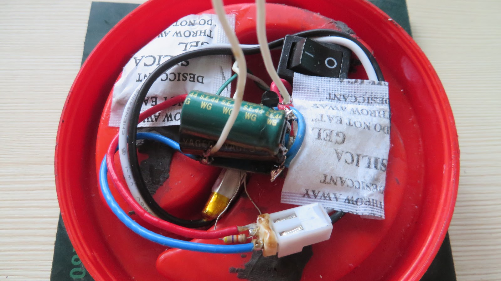
| Remember those tiny silica bags they put in shoe boxes? I decided to incorporate a couple of those inside the jar. They will supposedly sick away all the moisture that accumulates inside the jar over time. |
 |
| I also hot-glued everything to make it more stable. |
Enjoy!
Well, it was an interesting project for someone starting to dabble in energy harvesting and solar power particularly.
As a side effect, it culminated in something useful that you can hang in your garden, which is a plus!
Finished look:
 |
| Now's time to take off the protective film. If you were to take it off earlier, the surface would be dirty, therefore less permeable to light. If you did it now - look how it shines! |
 |
| It's not much use if it just stands on a surface. I weaved this hanger thingy out of an ordinary twine to be able to hang it anywhere. |
 |
| My glass jar lamp at nighttime. |


Comments
Post a Comment