- Get link
- X
- Other Apps
На русском
Back when I was only starting to dabble in electronics, I needed a project that would meet the following requirements:
Everyone is familiar to the ever-living problem with switching the lights off in your room before going to bed and stumbling back across the room. The IR switch I describe here solves that problem, and I can definitely tell that this project was a success - I am still using it with no regret.
As usual, I am putting up the link for source code, schematic and PCB at the end of the article.

The schematic is pretty straightforward. Although it may be simple for me, this device is intended for absolute beginners in electronics so I'll try to explain every bit of it.
Power is supplied from an external 5V power supply (not sure about current, should be a tiny figure). There's C1 for filtering ripples in power supply, it's an electrolytic capacitor and the value doesn't matter really much, can be anywhere from 10 to 1000uF. There's also C2 and C3 for the same purpose, and those are placed as close as possible to the point of consumption, that is, to microcontroller's power supply pins.
The heart of the circuit is ATTiny2313 clocked at 8MHz. C4 and C5 are load capacitors for crystal. There's input - the switch S1 with debouncing circuit and IR receiver designed specifically for reception of 36KHz pulses (TSOP1736); and then there's output - the relay which is switched on and off by means of a simple bipolar transistor. Diode D1 supresses the voltage spikes that appear at the time of switching across the relay coil.
The only thing leaft is an ICSP header that I use to program my microcontrollers soldered on the board. And that's it, really.
Next step would be modifying (the code my remote sends when I press the OFF button may be different from what your remote sends, just edit the code) , compiling and uploading the firmware and installing the new smart switch in place of the old dumb one:

Hardware in Eagle and C code for AVR
That's it, no more cold feetsies for ya!
Back when I was only starting to dabble in electronics, I needed a project that would meet the following requirements:
- simple to make;
- original (i.e. done entirely by myself from scratch);
- containing a microcontroller;
- and maybe the most important of all, useful. I've had enough devices I assembled just to dismantle the whole thing a month later.
Everyone is familiar to the ever-living problem with switching the lights off in your room before going to bed and stumbling back across the room. The IR switch I describe here solves that problem, and I can definitely tell that this project was a success - I am still using it with no regret.
 |
| That's what it looks like. The blue cover is a lid from some beauty product. |
As usual, I am putting up the link for source code, schematic and PCB at the end of the article.
Parts
- ATTiny2313 (datasheet),
- ICSP header - 10 pin or 6 pin variety,
- TSOP1736 IR receiver,
- 5v coil relay,
- various other petty parts.
Schematics
The schematic is pretty straightforward. Although it may be simple for me, this device is intended for absolute beginners in electronics so I'll try to explain every bit of it.
Power is supplied from an external 5V power supply (not sure about current, should be a tiny figure). There's C1 for filtering ripples in power supply, it's an electrolytic capacitor and the value doesn't matter really much, can be anywhere from 10 to 1000uF. There's also C2 and C3 for the same purpose, and those are placed as close as possible to the point of consumption, that is, to microcontroller's power supply pins.
The heart of the circuit is ATTiny2313 clocked at 8MHz. C4 and C5 are load capacitors for crystal. There's input - the switch S1 with debouncing circuit and IR receiver designed specifically for reception of 36KHz pulses (TSOP1736); and then there's output - the relay which is switched on and off by means of a simple bipolar transistor. Diode D1 supresses the voltage spikes that appear at the time of switching across the relay coil.
The only thing leaft is an ICSP header that I use to program my microcontrollers soldered on the board. And that's it, really.
Hardware
Now that the theory is behind you can start etching the PCB and assembling the device. My looks awful after lots of modifications of the original design, but here it goes:
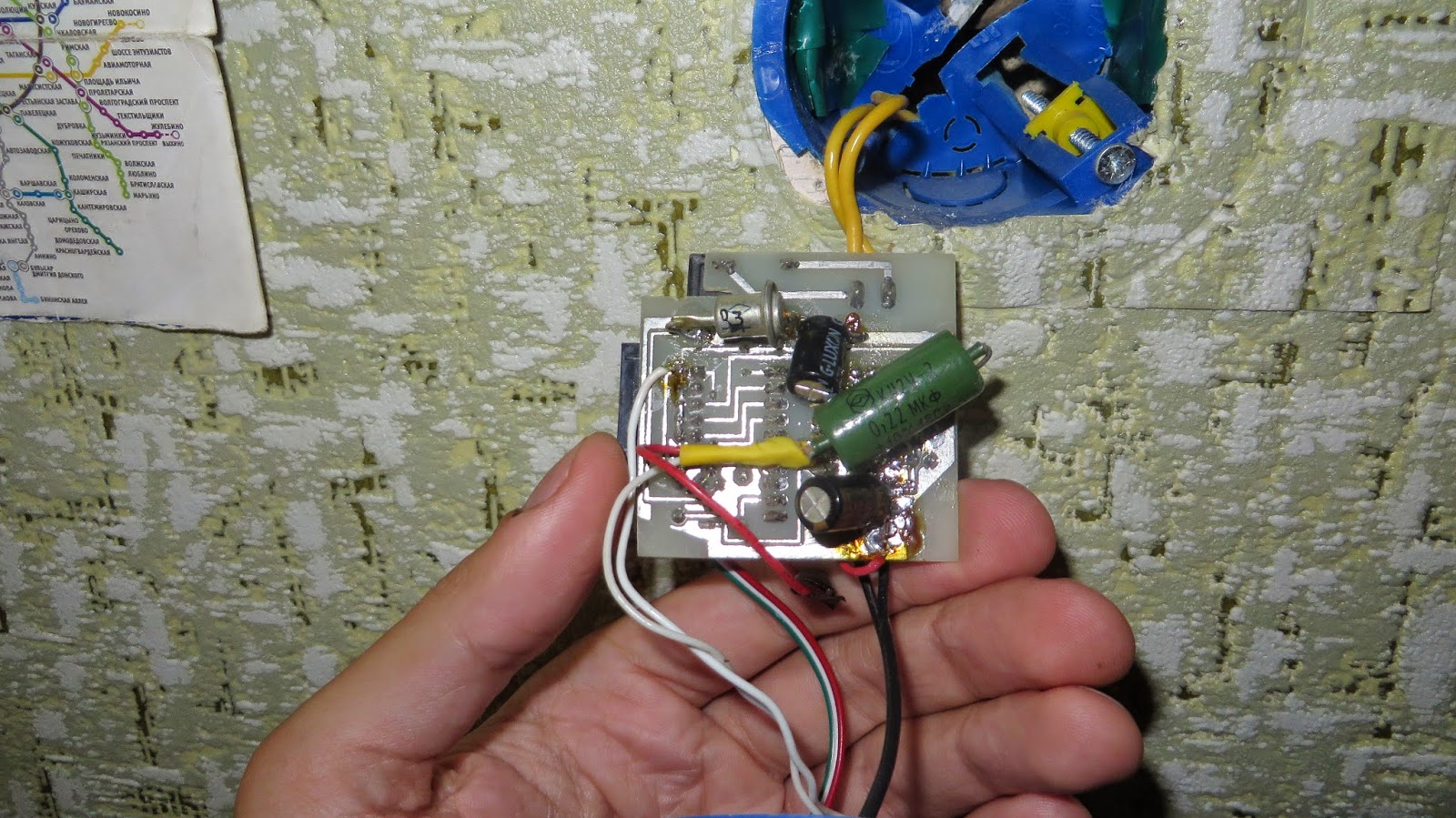
|
| Your switch is not supposed to look like crap, unlike mine. |
Next step would be modifying (the code my remote sends when I press the OFF button may be different from what your remote sends, just edit the code) , compiling and uploading the firmware and installing the new smart switch in place of the old dumb one:
Hardware in Eagle and C code for AVR
That's it, no more cold feetsies for ya!
This is an open-source hardware, you are free to modify whatever you want.
Could You please save project files in Eagle with a little bit older version. We simply can't open v7.1 files. :-(
ReplyDeleteI don't see such option in my software, which means you're on your own. I'm sure you're not the only one with that problem, try to google it.
Deletegood project but You should also include an AC/DC power supply into design and close it into single cover.
ReplyDeleteGoodbye, my cold feet!))) ;-)
ReplyDelete