- Get link
- Other Apps
На русском
See PART 1 here.
This blog post is a part of series about really cheap GSM/GPRS module Neoway M590:
- Neoway M590 GPRS Tutorial: sending and receiving files from/to SD card
- Application of Neoway M590: remote control for garage heater
- SMS GPS-tracker with Neoway M590 and ublox NEO-6 part 1. Gathering parts and testing
Here's some helpful links with datasheets:
- Neoway M590 Hardware design manual
- Neoway M590 AT command set
- ublox NEO-6 datasheet
- ublox NEO-6 receiver specs
- ATMega 328P datasheet
SMS GPS-Tracker schematic and assembly

Correspondence of Arduino pins to physical ATMega pins was determined thanks to this helpful drawing:

As you may have noticed, there's a new pin that wasn't there before - DTR pin on Neoway M590. That pin is utilized to put GSM module to sleep mode. Current consumption in sleep mode is decreased tenfold, so that's something to be desired.
Unfortunately, my breakout board didn't expose DTR pin on module's pin header. We'll have to make some corrections:
The next logical step would be to plug the soldering iron and to rummage about your workshop for a small piece of perfboard.
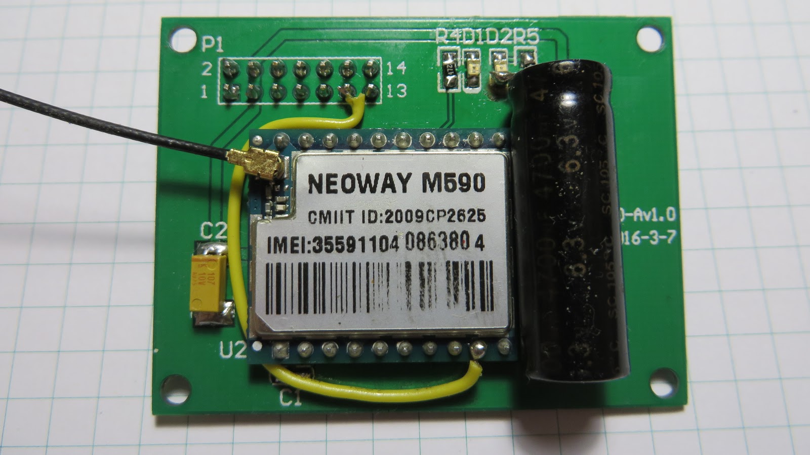
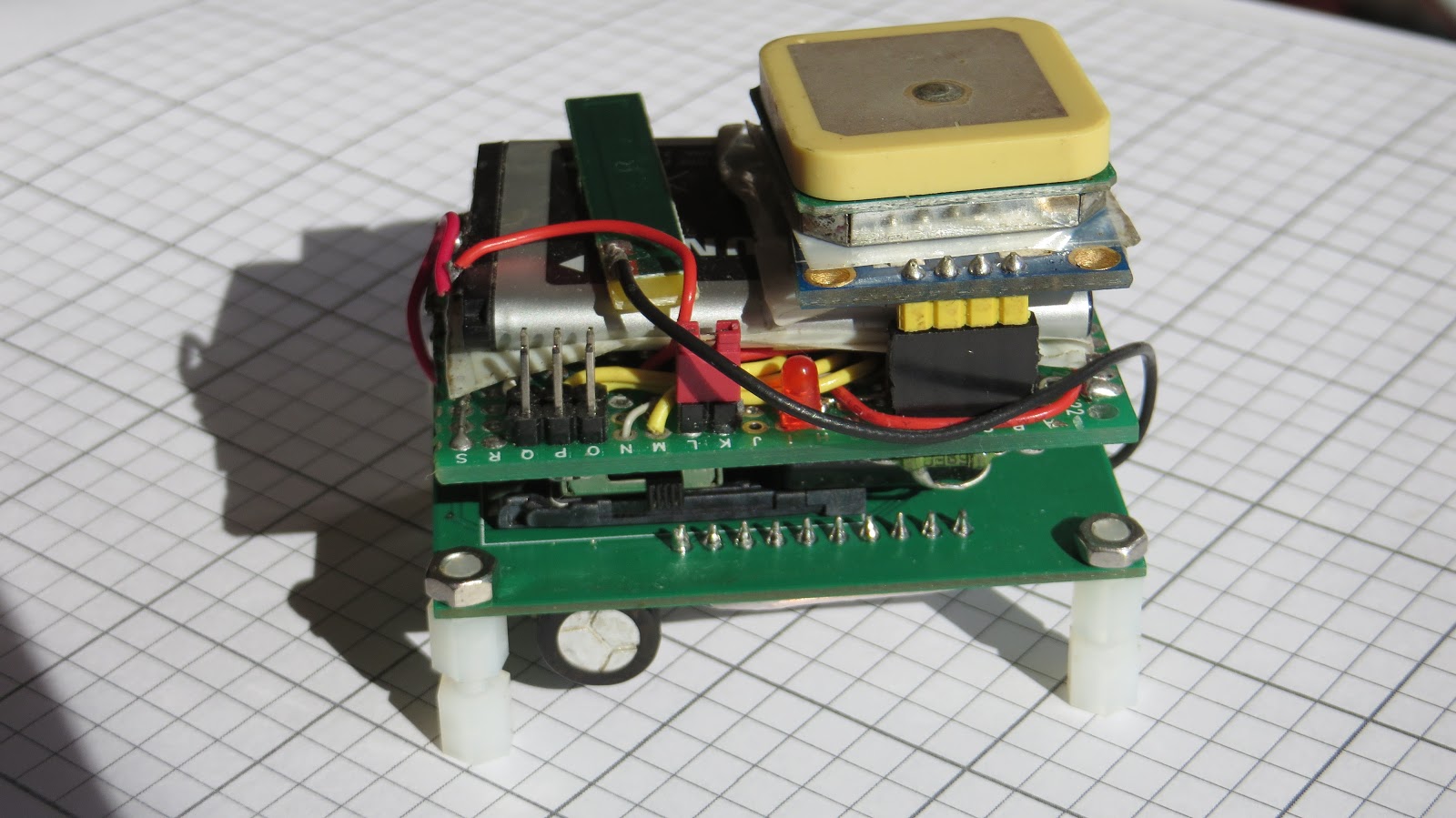
My build is fashioned in sandwich form factor. This kind of style seemed to yield the most compact device I could think up. Boards are arranged as three layers: topmost (bottom actually, the first picture is just upside down) is occupied by Neoway M590 module with its huge current peak filtering capacitor, middle with ATMega and all the custom electronics and bottom (top, really) with GPS board and both antennae (that's why it should be considered top, you'll want to position your antennae on top of our build).
Here's some pictures of GPS tracker mid-assembly:
|
|||||
 |
 |
||||
|
|
||||
|
 |
||||
|
|
||||
 |
|
||||
|
|
||||


After flicking the switch on, nothing should heat up and emit smoke. In case it does, recheck all your connections and try again. As soon as your hardware is in working order, you may move on to coding...
 |
| Device ready! |
Programming
That choice of ATMega328 was no coincidence, I specifically chose it to simplify things and write my firmware with Arduino.Get your trusty programmer and connect it to the 6pin connector.
That's the programmer I use (links to adapter and programmer):
 |
| USBASP programmer + 10 to 6 pin adapter. |
Fire up the Arduino IDE and try to flash any example to just check the connections are good and the chip is working: pick your board and programmer in settings and click "Upload using programmer" (Ctrl+Shift+U on most operating systems).
|
|


That simple trick didn't work for me (they seldom do, nothing ever works out of the box, gaah).
 |
| And that, kids, is how you debug your stuff... Personally I always keep it ticked. |
Having enabled verbose mode for uploading in Arduino IDE, I faced the following wall of error text:
After a couple of hours of investigation, I found the root cause of the error. Apparently, ATMega328P chips come pre-programmed to use internal 1MHz oscillator from the factory. That's way too slow to program them using USBASP with settings that IDE invokes it with.
The first thought that came to me after figuring this out was: "Now, that's nice and all that I know why it doesn't work, but how do I check if my chip and connections are good?"
For that you'll need avrdude tool. Execute this line to check your connections without any modifications to controller's firmware (taken from stackexchange):

OK, so your ATMega is working and can be programmed. Now, as for the workaround: first, create a new 'Slow' version of programmer for Arduino IDE. Modern versions of IDE hide this file deep in your user's folder (for Windows it'll be C:\Users\YourUser\AppData\Local\Arduino15\packages\arduino\hardware\avr\version)
 |
| Had to dig a little to find where these are hidden... |
Restart Arduino IDE, select 'Slow USBASP' programmer from list and try to upload again... It works! Blink.hex uploads, although the blinking frequency seems... slow. 8 times slower than programmed, to be precise. What's that about? Peer at the uploading log again... There it is! The fuse settings are all wrong!
> avrdude: safemode: Fuses OK (E:FF, H:D9, L:62).
Doesn't look OK to me! Somehow, even though the fuse settings are specified for each board in boards.txt, IDE doesn't burn the correct fuses even if the device's fuses are wrong. Fuses are only set when you burn the bootloader, and I don't really need it.
AVRDude just needs a little shove in the right direction to burn the right fuses. Let's just keep Arduino IDE open (so that Blink.hex stays in the same place), copy the command that uploads Blink.hex to your chip and execute it in console with a little something added at the end:
That should solve anomalous speed of AVR chip! By now, you can switch back to ordinary USBASP programmer configuration in Arduino IDE since the chip is clocked at 8MHz now.
Arduino sketch
Now, here's the full program that sends you back GPS coordinates (optionally you can include GPS date and time and SIM balance) in response to your call (with no power saving). You'll need to install the libraries AltSoftSerial and NeoGPS to make this work:I had to circumvent one notable drawback of AltSoftSerial library, that is the fact that all functions that depend on Timer0 become unusable - delay() and millis(). To get my lovely delays back, I use Serial's setTimeout() function, hence the newDelay() function.
The same sketch with power saving is coming up sometime soon... For now though you can safely use this one to get tracker's coordinates as a Google Maps link in response to your call. It'll just drain your battery sooner than you'd like.
UPDATE 4 July 2017
This one sends you the same data as the previous code, only WITH power saving enabled. You'll need to additionally install LowPower library. ATMega and GSM modem spend most of their time in energy-saving mode until someone calls or sends a text.What you can do now to further save battery is desolder the power LED on Neoway M590 PCB. Now we're saving extra 20mA, which is nice!
Any idea is the M590 going to work in USA ?
ReplyDeletein the speck it say Quad Bank , but mention only 900/1800 and USA is 850/1900 ....
Not sure which spec. sheet you looked into, but the hardware design manual states that frequency bands are as follows:
Delete900/1800 or 850/1900 or quad-band.
...btw I thought they phased out 2G altogether in US, so 850/1900 still being around is news to me.
How long this could live with the battery
ReplyDelete